For today’s group meeting, only the IRAM members (Xing, Robert, and Ashley) were in attendance. We primarily discussed the big picture scope of our project and the upcoming Photonics West presentations. Read More “Group Meeting 10/23/15”
Month: October 2015
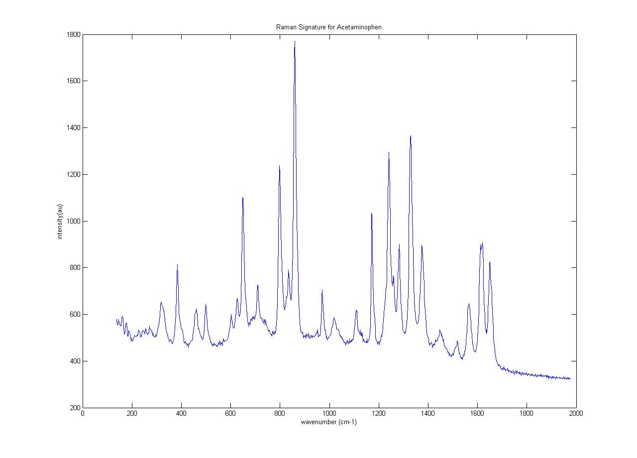
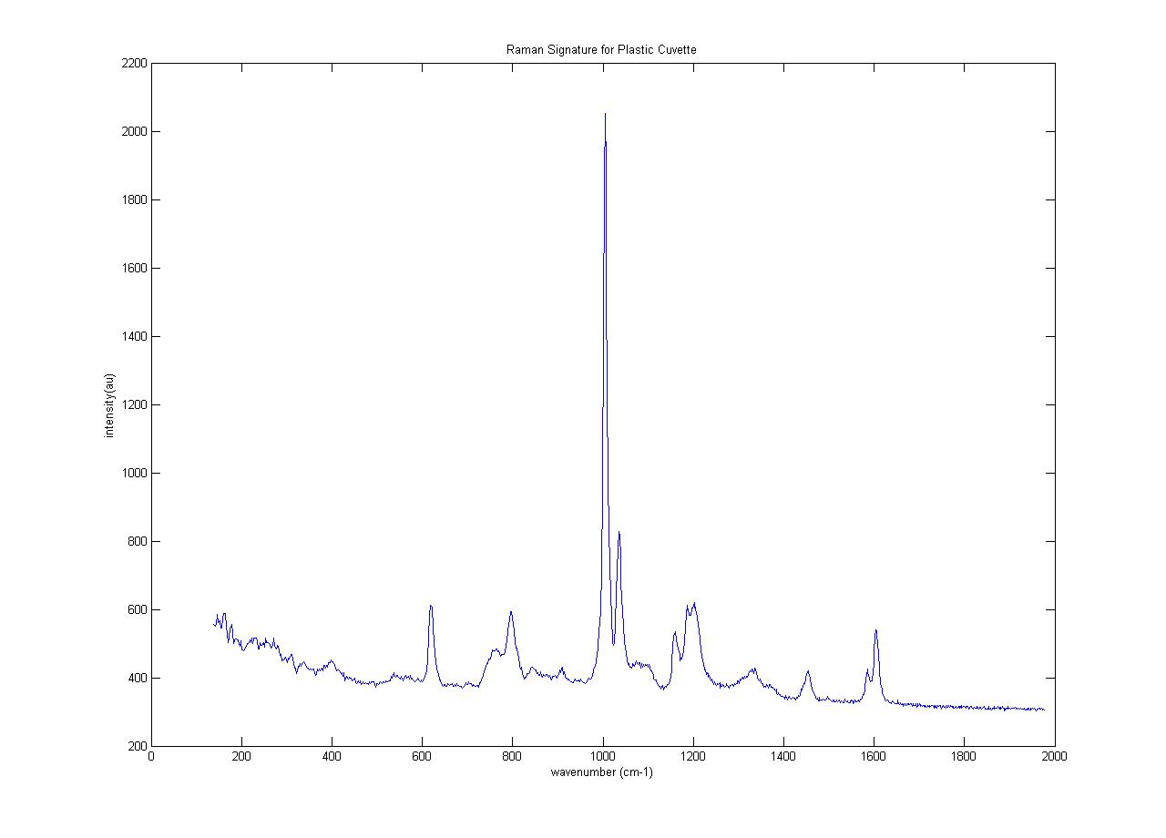
Raman Signature for Plastic cuvette and Acetaminophen using Confocal Raman Microspectroscopy system
Throughput vs angle correction
To our knowledge, the throughput of our system versus angles has not previously been accounted for. To determine it, we placed the teflon cap in the sample chamber, submerged it in water and put a square coverslip on top, just as we would for a bead sample. The scattergram for the cap is shown below.
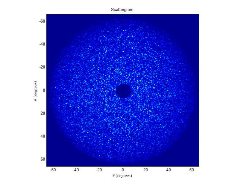 If the throughput did not change versus angle, then the intensity should be about constant (with noise) throughout the entire scattergram.
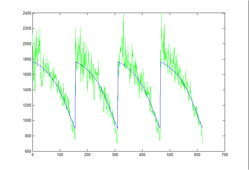
 However, we can tell from the cut-throughs that there is indeed a falloff. This falloff can be well fit to a cos(theta) function: Throughput(θ)=I(θmin)cos(θmin)cos(θ)
 Here is the least squares fit to a 5um bead without any throughput correction:
 And here is the fit with the throughput correction. The theory cut-throughs were multiplied by the above throughput equation and then least square fit to the data (with an offset and stretch term).
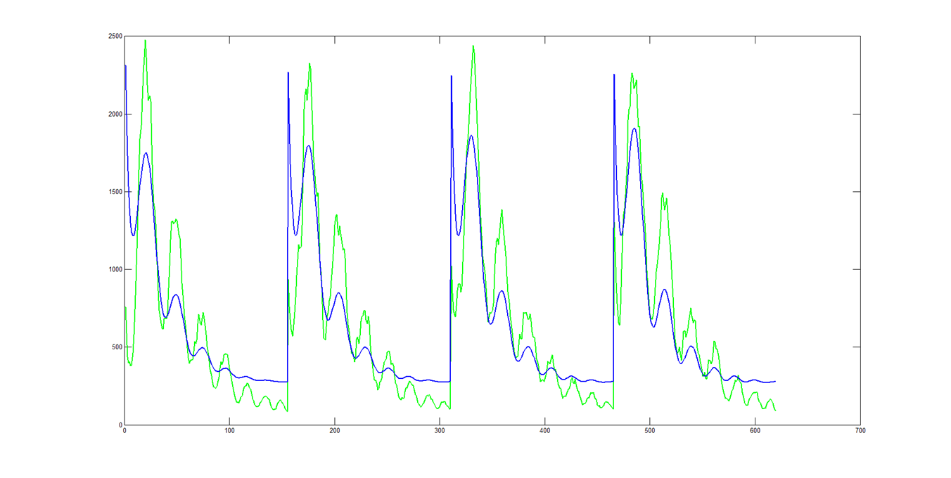 The throughput correction did not have much of an impact on the quality of the fits. If instead you LSF the theory cuts to the data, like normal, and then multiply by cos(θ):
 The amplitudes of the peaks are still to small, but the falloff trend seems more correct.
Reference beam setup/alignment
- If pellicule beamsplitter is out, put it in between the CCD and the last lens of the 4f system. The engraved side should be facing away from the CCD. It should be at as much of a 45 degree angle as possible, given the space constraints. Make sure the beamsplitter is not clipping the sample beam.
- Direct the reference beam towards the CCD using reference mirrors 1 and 2.
- With all ND filters out, adjust reference mirror 1 so that the reference beam transmitted through the pellicule and the sample beam reflected off of it hit the same spot in the near field (close to the pellicule).
- Adjust reference mirror 2 so that the two spots overlap in the far field (farther away from the pellicule).
- When the spots are very close to overlapping, it may be beneficial to stop down both beams so that the spot sizes are small. Just make sure the iris’s used are centered!
- Put the ND filters back in, and make final adjustments to mirror 1 so that the two beams overlap perfectly.
- If this part of the alignment is correct, you should have circular fringes with good contrast.
- Put a sample of fixed beads into the system (larger beads make alignment easier).
- Place a bead on the edge of the elastic excitation beam, diagonal from the center. Adjust BS1 and reference mirror 1 so that the tilt fringes are nulled in the interferogram.
- Move the bead to the center of the excitation beam. Adjust the BS and mirror until the frequency of the tilt fringes approximately doubles in both x and y directions.
- Put in two pinholes along the reference beam path to make future alignments easier.